
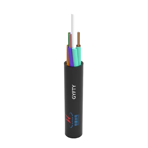
Optical cable represents a sophisticated transmission medium engineered specifically for high-speed data communication through light signal propagation rather than electrical impulses. As telecommunications infrastructure evolves toward unprecedented bandwidth demands, optical cable has emerged as the cornerstone technology enabling modern network architectures across metropolitan areas, data centers, and enterprise environments. These specialized cables consist of ultra-pure glass or plastic fibers, typically measuring between 8 to 125 micrometers in diameter, encased within protective layers designed to withstand diverse environmental conditions. The transmission mechanism relies on total internal reflection principles, where light signals bounce through the fiber core at velocities approaching 200,000 kilometers per second, delivering data rates from 1 Gigabit to 400 Gigabit per second across distances ranging from 100 meters to 40 kilometers depending on configuration.
Modern optical-cable deployments span indoor and outdoor builds and are anchored in specific standards and numeric limits: indoors, tight-buffered or micro-tube cables with 2–144 fibers carry OFNP/OFNR ratings under NEC Article 770 and often use LSZH jackets to reduce smoke toxicity in plenum/risers, enabling dense routing in data centers and commercial spaces outdoors, loose-tube designs add dry or gel water-blocking, UV-stabilized sheaths, and tensile members (aramid/FRP/steel) to survive aerial, duct, and direct-burial installs, while ADSS variants serve power-pole spans at the fiber level, PCVD/MCVD/OVD processes yield single-mode cores of 8–9 µm for long-haul windows (1310–1550 nm) and multimode cores of 50/62.5 µm for short-reach links, standardized as OM1–OM5 and OS1/OS2, where OM classes are defined in ISO/IEC 11801 (e.g., OM4 ≥ 4700 MHz·km at 850 nm; OM5 supports 850–953 nm SWDM with ~2.3 dB/km attenuation at 953 nm), and OS categories reference ITU-T G.652 low-water-peak fibers for wideband use ; accordingly, bend-insensitive G.657 fibers permit tight installation radii—A1 ≈ 10 mm, A2/B1 ≈ 7.5 mm, B2 ≈ 5 mm—without marked penalty, which is why they dominate FTTH drops and building interiors; in practice, installers observe minimum bend rules (≈ 10× cable OD static/20× dynamic) and tensile limits on pulls, then verify links by Tier-1 OLTS loss and OTDR traces, with widely cited cabling limits of ≤ 0.3 dB per connector and ≤ 0.05 dB per fusion splice for quality work (TIA/ISO guidance and FOA/T&M references) ; finally, for high-density interconnects, LC/SC and MPO/MTP terminations are paired with UPC/APC polishes to meet return-loss targets (≈ ≥ 50 dB UPC/≥ 60 dB APC) and to keep cumulative budgets within design, so, for example, a 10 km OS2 link at 1310 nm with four connectors and four splices typically lands near ~5.9 dB end-to-end loss using standard allocations, comfortably under common 8 dB optics budgets for metro and campus backbones
What is MPO Cable?
MPO cable assemblies provide very high port density by consolidating 8/12/16/24 fibers in common data-center builds and even 32/48/60/72 fibers for specialty arrays, all within a single MT-ferrule interface, thereby shrinking footprint without sacrificing aggregate bandwidth; intermateability and the male-with-pins/female-with-guide-holes scheme are formally defined by IEC 61754-7/-7-1 and TIA/EIA-604-5 (FOCIS-5), while polarity methods (Types A/B/C) are covered in ANSI/TIA-568.3 to maintain end-to-end Tx/Rx mapping. In practice, the MT ferrule enforces 250 µm fiber pitch, 0.7 mm guide pins at 4.6 mm separation and tight molding tolerances for array alignment, and reputable vendors publish performance grades for low-loss single-mode and multimode variants. Beyond generic MPO, US Conec’s MTP® platform adds mechanical upgrades such as metal pin-clamps and serviceable/removable housings, and its MTP® PRO enables in-field pin (gender) and polarity changes, easing moves/adds/changes in high-density environments. End-face quality is controlled by IEC 61755-3-31, which specifies MT geometry (e.g., array polish angle, fiber height differential, and coplanarity) to minimize insertion/return-loss; cleanliness is verified to IEC 61300-3-35, and many MT parts now claim Grade-B conformance for low-loss performance. For durability, mainstream specifications and vendor data target ≥ 500 mating cycles (TIA-568.3 requirement), with high-quality MTP implementations typically surviving > 1000 under proper inspection/cleaning; published datasheets from multiple suppliers cite the same 500-cycle benchmark. Regarding optical figures, reputable catalogs list ultra-low IL options around ≤ 0.35 dB per mated pair , while return-loss targets follow polish type—multimode PC ≥ 20 dB and single-mode APC often ≥ 60 dB—provided geometry and cleanliness meet spec. Finally, because MT arrays can be built in multi-row formats (e.g., 6×12 = 72 fibers), designers can scale parallel-optics links and cassette modules without multiplying discrete connectors, so long as they lock polarity, keying, and pinning to the cited standards and verify each trunk with Tier-1 loss testing and end-face inspection per IEC guidance.
MPO cable configurations support multiple polarity methods designated as Type A, Type B, and Type C, each defining specific fiber-to-fiber mapping schemes essential for maintaining signal integrity in duplex and parallel optical systems serving 40GBASE-SR4, 100GBASE-SR10, and 400GBASE-SR16 Ethernet standards. Trunk cable implementations commonly feature 12-fiber MPO terminations at both ends with either OM3 multimode fiber supporting 10 Gigabit transmission across 300 meters, OM4 specifications enabling 100 Gigabit over 150 meters, or OS2 single-mode variants extending reach to 2 kilometers for PSM4 applications and 10 kilometers for LR4 deployments. Breakout configurations transform single MPO interfaces into 4, 6, 8, or 12 individual LC duplex connections through fanout assemblies incorporating 2.0mm buffered fibers, enabling flexible adaptation between high-density backbone infrastructure and server/storage endpoints. Performance specifications mandate insertion loss values below 0.35 dB for elite-grade products and return loss exceeding 60 dB for single-mode installations, with testing protocols validating compliance against IEC 61754-7 and TIA-568 standards. Contemporary data center architectures extensively deploy MPO technology within spine-leaf topologies, supporting 100G and 400G switch interconnections while achieving port densities 12 times greater than conventional duplex LC solutions.
Go further — explore more paths that challenge convention and spark insight.