
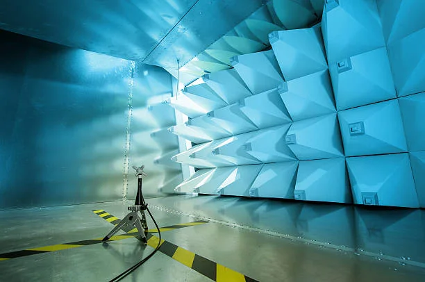
Picture trying to test a new wireless device in a typical laboratory. Signals from WiFi networks, nearby equipment, and even cell phones create a chaotic electromagnetic environment. Getting accurate readings becomes nearly impossible when radio waves bounce off every surface RF anechoic chamber.
That’s where an RF anechoic chamber comes in. These specialized rooms absorb electromagnetic waves rather than reflecting them back. The word “anechoic” literally translates to “no echo,” which describes exactly what happens inside. Radio frequency signals act as though the device sits in open air, miles from any interference. Companies working on 5G technology, IoT devices, or vehicle communication systems can’t afford to skip this step.
Regular testing environments suffer from multipath interference. Signals reflect off walls, equipment, and even people walking by. These reflections create false readings that hide a device’s actual performance. An anechoic RF chamber eliminates these issues entirely, which explains why serious wireless development relies on them.
Finding the Right Size and Type
Not all RF anechoic chambers are created equal. The testing requirements for a Bluetooth chip differ dramatically from those needed for a complete vehicle communication system.
Chamber size depends on what needs testing:
- Desktop chambers handle small components like antennas and sensors
- Mid-sized chambers accommodate smartphones, tablets, and consumer devices
- Walk-in chambers test vehicles, industrial equipment, and large-scale systems
Chamber dimensions matter for another reason, too. Far-field distance calculations might sound technical, but they’re straightforward. Antennas need specific spacing from the test equipment to get proper measurements. Take a typical smartphone antenna running at 2.4 GHz—it needs about 1.4 meters of clear space. The chamber has to fit that distance plus whatever the absorber materials take up.
Semi-Anechoic vs. Fully Anechoic Configurations
This decision shapes everything that follows. Semi-anechoic chambers have absorbers on the walls and ceiling, but keep a reflective metal floor. This setup mimics real-world conditions for automotive systems and ground-based equipment that naturally operate near reflective surfaces.
Fully RF anechoic chambers take things further by covering all six surfaces with RF-absorbing material. These chambers create the truest free-space conditions possible and excel at precise antenna pattern measurements. The downside? Higher costs and a somewhat disorienting work environment due to complete acoustic absorption.
Technical Specifications That Actually Matter
Getting the technical details right separates successful chamber implementation from expensive mistakes. Three factors deserve special attention.
Frequency Range Compatibility
Every chamber has limits defined by its absorber materials. Lower frequencies present unique challenges. Anything below 1 GHz needs thicker absorber materials since longer wavelengths penetrate deeper. That’s why many chambers use hybrid absorbers—ferrite tiles paired with foam pyramids—to cover frequencies starting at 30 MHz.
The story changes at higher frequencies. 5G devices working at 28 GHz or 39 GHz need pyramidal foam absorbers built to exact specifications. Here’s something interesting: taller pyramids handle lower frequencies better, which seems counterintuitive at first.
Getting the frequency range wrong causes real problems. Test results become questionable, and compliance testing often fails. The solution? Identify the complete frequency spectrum the device uses, then add a 20% safety margin on both ends.
Blocking Outside Interference
WiFi routers, cell towers, and other lab equipment constantly broadcast signals that mess with test accuracy. RF anechoic chambers solve this with conductive shielding made from copper or galvanized steel wrapped around the entire structure.
Professional testing usually requires 100 dB of shielding at a minimum. That level blocks signals by a factor of 100,000. This reduces external signals enough to eliminate interference from everything except the most powerful nearby sources. Military and aerospace testing sometimes requires 120 dB or more.
Absorber Technology
The pyramidal foam structures lining the anechoic chamber RF testing facilities consist of carbon-impregnated polyurethane. Pyramid geometry affects performance dramatically. Most pyramid absorbers stand 18 to 24 inches tall. Some specialized setups use 36-inch or even 48-inch pyramids when low-frequency absorption needs a boost.
Meeting Regulatory Standards and Managing Costs
Each industry follows its own set of testing rules. Picking the right chamber means understanding which standards apply to your products.
Key regulatory frameworks include:
- CISPR standards for consumer electronics
- CISPR 25 for automotive applications
- MIL-STD-461 for military and aerospace systems
- IEC standards for medical devices under FDA jurisdiction
Certification bodies increasingly scrutinize test facilities themselves. Chamber calibration records and measurement procedures become part of compliance documentation.
Budget Reality Check
Desktop RF shield boxes start around $15,000 and work well for testing individual components. Mid-sized rack-mount options run anywhere from $50,000 to $150,000 based on what features you need. Walk-in facilities for vehicle testing? Those can hit $250,250 or exceed $1 million.
Should you buy or rent? That depends on how often testing happens. Renting chamber time makes sense for companies with occasional needs. Organizations with ongoing development programs typically achieve better value by owning their facilities despite higher upfront costs.
Hidden expenses add up quickly. Installation requires specialized labor for proper grounding and shielding. Climate control affects measurement accuracy and absorber longevity. Maintenance contracts, calibration services, and eventual absorber replacement contribute to total ownership costs.
Planning for Future Needs
Wireless technology evolves rapidly. Chambers purchased today must accommodate tomorrow’s requirements. The 4G to 5G transition proved how quickly frequency needs can shift, leaving many existing chambers unable to support new millimeter-wave testing.
Automation and Integration
Modern testing demands efficiency that manual processes can’t deliver. Positioning systems can rotate devices automatically, capturing radiation patterns from every angle. The real question is whether the software ties everything together smoothly enough to actually save time.
Vendor Support Matters
Technical specifications only tell part of the story. Manufacturer expertise and support capabilities deserve equal consideration. Companies that design and manufacture their own absorber materials demonstrate a deeper understanding than those assembling third-party components.
Calibration and verification services separate professional suppliers from basic equipment vendors. An anechoic RF chamber requires periodic validation to ensure performance remains within specifications. Some manufacturers drop off equipment and leave installation to the buyer. Others handle everything—site surveys, installation oversight, and final performance checks.
Conclusion
Finding the right RF anechoic chamber means weighing technical needs against available budget while thinking ahead to future requirements. Write down the specifics first: how big are the devices, what frequencies need testing, which standards apply, and how much testing volume to expect. Visiting working chambers helps tremendously. Seeing the setup in person and hearing from people who use them daily reveals details that spec sheets never mention. The performance data gathered during development affects everything downstream—product success, passing regulatory checks, and customer satisfaction all hinge on reliable test results.
Don’t stop here—see how this theory actually works in practice at 2A Magazine.