
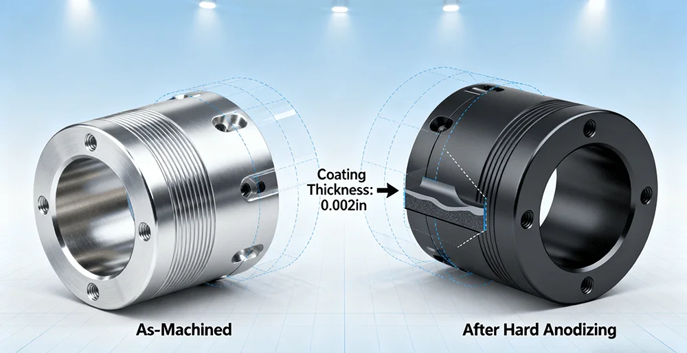
Figure 1: Visual representation of dimensional change in a CNC part after hard anodizing. The coating growth can cause fit issues if not accounted for in design.
Introduction
You’ve invested significant time and budget into machining a batch of precision aluminum components. The CNC – machined pieces come off the machine looking flawless, meeting every dimensional callout on the drawing. But after they return from the hard anodizing process, disaster strikes. Pins no longer fit into holes, threads bind, and critical sealing surfaces are compromised. The entire batch is scrapped, leading to costly delays and frustration. This common scenario often stems not from poor machining or anodizing work, but from a fundamental oversight in Design for Manufacturing (DFM). This article reveals three critical, yet frequently ignored, DFM principles that ensure your parts survive the rigors of hard anodizing.
Open this related post for fresh perspectives that support your next step.
Principle #1: Ignoring the “Invisible” Growth – Coating Thickness Compensation
The most common failure point is neglecting the physical thickness added by the anodic coating. Hard anodizing, or Type III anodizing, isn’t a paint; it’s a conversion process that grows a dense, porous aluminum oxide layer from the base material. This growth changes the final dimensions of the part.
- The Problem: A typical hard coat can add 0.0005″ to 0.002″ (12µm to 50µm) per surface. For a pin that must fit into a hole, this effectively increases the pin’s diameter and decreases the hole’s ID. The result is an interference fit where a slip fit was intended. This is catastrophic for threaded holes, press-fit bearings, and tight-tolerance assemblies.
- The Solution: Proactive dimensional compensation is non-negotiable. For critical features, you must design in specific allowances. For an H7/g6 sliding fit, you must intentionally oversize holes and under size shafts in the CNC machining stage to accommodate the post-anodize thickness. The required compensation depends on the specified coating thickness.
| Design Feature | Recommended Compensation (Per Surface) |
| Bore/ID (Hole) | Increase machined diameter by 2x the specified coating thickness |
| Shaft/OD (Pin) | Decrease machined diameter by 2x the specified coating thickness |
| Threads | Avoid anodizing pre-cut threads; specify post-anodize tapping or use oversized taps |
Principle #2: The “Current Density” Trap of Part Geometry
Hard anodizing is an electrochemical process. The part acts as an anode, and the coating thickness is directly influenced by current density—the amount of electrical current per unit area. Complex geometries disrupt uniform current distribution, leading to inconsistent coating thickness.
- The Problem: High-current-density areas like sharp external corners and edges will build up a thicker, more brittle coating. Conversely, low-current-density areas like deep recesses, blind holes, and sharp internal corners experience the “Faraday cage effect,” where the geometry shields the surface, resulting in an unacceptably thin, soft, and non-protective coating. This directly undermines the corrosion and wear resistance the process is meant to provide.
- The Solution & Authority Reference: Design for uniform current flow. The NASA/JSC PRC-5006 specification explicitly mandates that “corners shall have a radius, and not a chamfer or broken edge, to obtain a uniform coating.” It further provides a definitive table, correlating coating thickness with minimum recommended radii (e.g., a 0.06-inch radius for a 0.002-inch thick coat). This isn’t a suggestion; it’s a requirement born from the extreme reliability needs of aerospace. Ignoring this directly introduces a point of failure, as sharp corners create “dimensional irregularities” in the coating itself.
Principle #3: The Critical Link Between Surface Finish and Pretreatment
The quality and integrity of the starting surface dictate the quality of the final anodic coating. The anodizing process will amplify, not hide, any imperfections left by machining.
- The Problem: Visible machine marks (tool lines), contaminants (cutting oils), or variations in surface roughness (Ra value) can lead to poor coating adhesion, discoloration, and a mottled appearance. Embedded contaminants can cause pitting during the process.
- The Solution & Authority Reference: The NASA/JSC PRC-5006 specification offers a masterclass in this area, stating that “surface preparation is critical to the quality of the anodize” and that “the surface texture is replicated (not leveled).” This means a rough machined finish will result in a rougher anodized finish. Furthermore, standards like those discussed in ASTM STP12050S provide rigorous methodologies for testing coating adhesion and durability. These standards validate that without a properly prepared surface—whether for a glossy finish (requiring mechanical polishing) or a matte finish (requiring blasting)—the coating’s fundamental protective properties are compromised before the process even begins. This links CNC machining quality directly to the performance metrics defined by international standards.
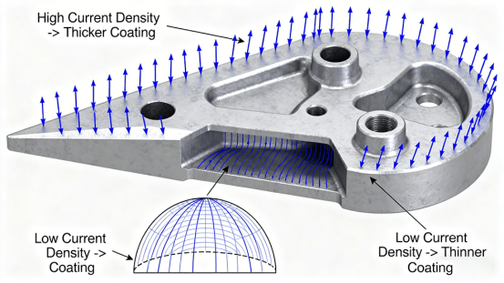
Figure 2: The “current density trap.” Complex features like sharp corners and deep holes lead to uneven coating thickness, a critical DFM consideration.
The Systemic Solution: Embracing DFM and Integrated Manufacturing
The root cause of these failures is often organizational: treating CNC machining and hard anodizing as two separate, sequential tasks. This “over-the-wall” approach creates communication gaps.
The most effective solution is to partner with a manufacturer that offers integrated CNC Machining Services and possesses deep expertise in surface treatment like What is anodizing. This collaborative, “Design for Manufacturing” (DFM) approach ensures integrated manufacturing:
- Design Review: Your part is reviewed for anodizing compatibility.
- Seamless Process Control: The transition from machining to pre-treatment happens under one roof.
- Unified Responsibility: One supplier is accountable for the final part.
By integrating manufacturing steps, you reduce project risk and improve communication efficiency.
Conclusion
Achieving reliable, hard-anodized parts requires more than precise machining. It demands a holistic view of the entire manufacturing process. By mastering these three DFM principles—dimensional compensation, geometry optimization, and surface finish control—and adopting an integrated manufacturing strategy, you can transform hard anodizing from a project risk into a guaranteed success factor.
FAQs
Q1: How much size allowance should I leave for a hard-anodized CNC part?
A: Plan for a total dimensional change of 2x the specified coating thickness per feature. For a 0.001″ (25µm) thick coat, a bore ID should be machined 0.002″ larger. Always consult with your manufacturing partner early in the design phase.
Q2: Can hard anodizing fill in machining marks?
A: No. Anodizing is a transparent conversion coating that will amplify surface imperfections. A smooth, clean machined surface is essential.
Q3: What are the color options for hard anodizing (Type III)?
A: Hard anodizing is primarily for wear and corrosion resistance. The process naturally produces dark gray to black shades. Dying is not typical for Type III.
Q4: My part has both large and very small features. Will the coating be uniform?
A: This is a significant challenge due to the current density effect. Small features will anodize faster. This often requires specialized racking, a key reason to work with an expert.
Q5: Why is an integrated CNC and anodizing supplier better?
A: It ensures seamless DFMapplication. The machinist understands the anodizing process requirements. It consolidates quality control and accountability.
Author Bio
This article is contributed by Jason Lee, who is a technical consultant at LS Manufacturing which is ISO 9001:2015 certified enterprise that provides integrated manufacturing solutions, including CNC Machining Services and rapid prototyping all under one roof. As an AS9100D, ISO 9001:2015, and ISO 14001 certified enterprise, the company ensures that client projects achieve precision, reliability, and cost-effectiveness from prototype to production.
Keep exploring—more content awaits to help deepen your understanding at 2A Magazine.